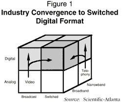
Recent progress in compressed digital video and multimedia technologies, combined with imminent local loop deregulation, has caused the cable television (CATV) operators and local telephone operating companies (telcos) to reassess the capabilities of their current and planned information distribution services networks. Both industries are moving toward a single, integrated services switching and distribution platform often referred to as a full-service network (see Figure 1). Hybrid fiber coax (HFC) technology has many characteristics that make it ideal for the next generation of distribution plant.
Since fiber optics is a very attractive medium for interactive broadband services, it is currently being used by both industries. The telephone companies would like to simply replace the existing copper-pair that connects every subscriber to the central office with optical fibers to eliminate the bandwidth bottleneck in the distribution. Many approaches have been offered by industry equipment suppliers to achieve a viable FITL (Fiber-In-The-Loop) solution, and the telephone companies have made many attempts to cost justify the technology. To date, however, no satisfactory solution has been found. Most FITL solutions have proven to be either too expensive or not capable of simultaneously transmitting broadband analog and digital services. Hybrid fiber coax distribution technology solves this simultaneous transport problem. It can also meet the demands of future services and the capacity and reliability requirements with minimal impact on existing plant.
Some of the reasons why HFC distribution is currently so interesting are summarized in Table 1. As can be seen, more than 30 Gb/s of digital information, over 2,000 movies, can be delivered downstream to a serving area, and more than 500 Mb/s can be provided back to the headend or central office albeit under managed reverse channel access conditions.
| Table 1: 750 MHz System Information Carriage Summary (500 Homes Passed at 60% Take) | ||||
| Distribution Direction | Bandwidth Allocated (MHz) | Information Distribution Capacity | ||
| NTSC Channels | Digital Capacity | |||
| Mb/s | Movies ** | |||
| Dowstream | 54-550 | 78 | X | X |
| 54-330 330-550 | 40 40 | 1,120 1,120 | 720 720 |
| 550-750 700 | 36 116 | 1,008 3,248 | 648 2,088 |
| Upstream * | 5-40 | 6 | 672 | X |
| * Enhanced Sub-Split provided for each distribution branch served by a Fiber Node (4 brances per node assumed). ** Assumes that each movie can be distributed using 1.5 Mb/s and that a 6 MHz channel can support up to 28 Mb/s. | ||||
| Source: Scientific-Atlantic | ||||
Hybrid fiber coax can accommodate all of the digital signal technologies of the telephone industry, such as TDM1 and PCM,2 and is naturally compatible with broadband carrier3 distribution systems. SONET,4 ATM,5 SMDS,6 and Frame Relay switching, multiplexing, and transport technologies are all compatible. Furthermore, these digital signals can be simultaneously distributed with standard NTSC7 television signals with no adverse affects. By comparison, the telephone industry still has not found a cost-effective method for distributing mixed analog and digital format services over a single distribution plant. Compatibility with the existing base of 140 million or so NTSC television sets that are in service today in the United States is a major stumbling block for digital distribution solutions. In order to be compatible with these television sets, all baseband digital video must be converted back to analog NTSC. This conversion process is expensive and is expected to remain a roadblock for perhaps the next decade.
Both the cable TV and the telephone operating companies have independently examined hybrid carrier distribution technology for broadband interactive services. U S WEST's Advanced Technologies Group (Boulder, Colorado) was the first telephone industry research group to solicit "line haul" technology solutions from equipment manufacturers for the local distribution of integrated broadband services. These broadband services include telephony, interactive multimedia, wide-area computer networking, video-on-demand (digital), and distance learning. Other telcos making commitments to HFC technology include Pacific Telesis, Ameritech, BellSouth, GTE, and Southern New England Telephone Company.
THE ARCHITECTURAL CHARACTERISTICS OF HFC DISTRIBUTION NETWORKS
HFC networks provide high performance at low cost because they can be designed to match the asymmetrical bandwidth needs of most broadband distribution systems. Architecturally, HFC networks are configured in a star or star-bus topology. The signal is transmitted from the headend or local distribution hub in a star-like fashion to the fiber nodes using fiber optic feeders. The fiber node, in turn, distributes the signals over multiple busses (star-bus) throughout the customer serving area. These coax busses provide highly cost-effective broadband distribution over the "last mile" of the network.
Hybrid fiber coax networks are similar to the Passive Optical Network (PON) designs that are very popular in FITL telecommunications networks. Both systems broadcast the downstream information to all users. When Time Division Multiple Access (TDMA) techniques are used on the HFC designs, both systems also have to perform station ranging8 in order to assure that no collisions occur when the subscribers transmit information upstream. Actually, HFC systems can use either baseband or RF carrier transmission techniques in the reverse transmission path (sub-split band). When RF carrier techniques are employed, either TDMA or Frequency Division Multiplexing (FDM) methods can be used. FDM, however, has several advantages over TDMA:
The cost-effectiveness of the coaxial bus distribution plant derives from the fact that each section of distribution coax not only brings signal to its subscribers, but also carries the signals for the subscribers served by the next section and so forth. Therefore, a given section of distribution bus serves not only its four or eight subscribers, but also provides the link to another possible 40 or 50 subscribers.
TODAY'S HYBRID FIBER COAX TECHNOLOGY
Today's hybrid fiber coax products provide a high-bandwidth, economical solution. A typical configuration provides 750 MHz to the home and can be upgraded, with no change in the coaxial cable distribution plant, to greater than 1 GHz performance simply by changing out the original line amplifiers.
HFC SYSTEM PERFORMANCE SPECIFICATIONS
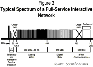
A typical performance specification for a 750 MHz system (upgradable to 1 GHz in the future) that operates 78 NTSC analog carriers in the 54 MHz to 550 MHz band and switched digital video services in the 200 MHz band between 550 MHz and 750 MHz is provided in Table 2. Each segment of a modern HFC design would be able to meet the link performance specifications provided in this table.
| Table 2 Typical Hybrid Fiber Coax System Specifications | ||||
|---|---|---|---|---|
| Performance Parameter | Local Hub | Fiber Node | Coaxial Tap | Subscriber Composite |
| Carrier-to-Noise (+dBc) | 58 | 51 | 54.5 | 48.8 |
| Composite-Triple-Beat (-dBc) | 70 | 66 | 57.0 | 53.0 |
| Composite-Second-Order (-dBc) | 70 | 64 | 59.0 | 57.5 |
| Cross Modulation (-dBc) | 65 | 63 | 59.0 | 52.5 |
| ||||
| Source: Scientific-Atlanta | ||||
TYPICAL HFC DISTRIBUTION PLANT COSTS
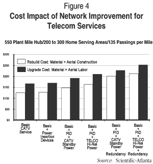
The total cost9 of an HFC distribution plant that can serve 200 to 300 homes with a density of approximately 135 passings per mile is around $125 per subscriber. When CATV standby power is added to increase service reliability, this cost rises to about $148. Adding telco-grade high-reliability power10 and diversity feeder routing in both directions raises the cost to an installed first cost of nearly $215 (aerial installation). The sensitivity of subscriber service cost to various distribution design parameters is detailed in Figure 4.
PASSIVE COAXIAL NETWORKS
The ultimate "fiber-to-the-last-device" architecture is called a Passive Cable Network (PCN). Today, these networks are economical only in full-service networks which can produce the necessary revenue. They provide the greatest possible return bandwidth per subscriber of any design.
As the distribution plant becomes more passive, it becomes more compatible with the telephone operating company industry's vision of large-scale switched broadband subscriber services. Will the downstream information capacity of the distribution plant be significantly reduced with passive networks? Will there still be a requirement to use broadband RF technology?
A quick calculation indicates that even with compressed digital video capabilities of 1.5 Mb/s per movie or television program, approximately 6 Mb/s to 10 Mb/s must be provided to every subscriber during the peak viewing hours. A serving area of 500 homes would require nearly 2 Gb/s of switched digital capacity (assuming 300 subscribers in the serving area). Delivering the required 10 Mb/s signal on demand to a given household using the baseband techniques will be prohibitively expensive far into the future.
Utilizing techniques developed for interactive switched digital services, 2 Gb/s can be delivered to a fiber node using as few as seventy 6 MHz video channels -- a standard 750 MHz system has a capacity of 120 video channels. Equally as important, this information does not have to be switched at the fiber node. The fiber node simply converts the signal from an optical to electrical format compatible with the subscriber's distribution coax. The subscriber's electronics equipment is instructed by the network traffic controller to tune to a specified 6 MHz channel and look for its data in a 28 Mb/s data stream. Both of these functions can be implemented reliably and cost effectively today.
Although the FCC limits the return path bandwidth from about 5 MHz to 40 MHz because Channel 2 must be carried untranslated in the downstream path, PCN networks can circumvent this constraint by using the signal spectrum above 750 MHz or 1 GHz for carrying return path information.11
SERVICE AVAILABILITY (NETWORK REDUNDANCY)
The issue of service availability will become more critical as subscribers use the network more often and for longer sessions. A television service outage at 8:00 p.m. on Saturday night, for example, will certainly be noticed by many viewers. On the other hand, unless a telephone goes out-of-order during a two- or three-minute telephone call, service outages may not ever be noticed. HFC networks will have to be designed to be more reliable and will have to be closely monitored on a continuous basis to provide maximum service availability.
HIGH-RELIABILITY SOLUTIONS
As "life-line" telephony and other important services are added to the HFC networks, several methods will have to be employed in parallel to improve service availability. First, all transmission routes will have to be protected. This may mean that the optical transmitters are protected on a one-for-one basis. It certainly means that the feeder path between the headend and the fiber node will have to be protected using an alternate cable route. The fiber nodes themselves will have to be modified to provide route diversity protection on both the downstream and upstream links. The reverse path optical transmitters will also have to be protected. The remote network powering units themselves will have to be internally protected. Batteries will be needed to protect against short-term power outages; longer-term outages will require power generators. Each fiber node will have to be fed by two different power nodes using a different cable route from each unit. Finally, damage to the coaxial cable distribution busses that feed the subscriber drops can cause the loss of service to a large number of subscribers. However, as HFC networks have migrated toward passive network designs, the largest subscriber group that can be affected by a network failure has dropped well below Bellcore's 64 subscriber requirement to failure group sizes as low as 32 subscribers.
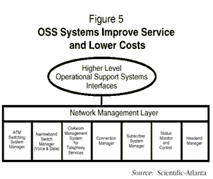
NETWORK MANAGEMENT
As the hybrid fiber coax network carries more and more services, performance monitoring and management are necessary to maintain the integrity of the information. Network problems must be quickly detected and resolved. Video signal quality is supervised by three different systems:
In order to manage the distribution of switched digital video services, a connection management controller is used. The trend today is to integrate all communications services delivery systems into a single network management system (see Figure 5).
SUBSCRIBER PRIVACY/SECURITY
Since the distribution segment of hybrid fiber coax networks is a bus, all users on the bus have access to all the other user information on the bus.13 Today, with inexpensive processing power and encryption chip technology, very high levels of security can easily be achieved. As far as the hybrid fiber coax network is concerned, however, it is totally passive and has no effect upon the signals themselves. In many ways, HFC systems are more secure than some of the fastest growing communications systems available today: about 95% of the cellular mobile radio and personal communications system signals can easily be monitored using standard radio scanners. If high-level privacy is desired, then the information source must encrypt the information before it is put on the network for delivery. This helps determine whose responsibility information security really is.
DISTRIBUTION CAPACITY.
The following parameters are typical of the technology that the majority of cable companies are deploying today:
| Downstream Bandwidth | 750 MHz |
| Reverse Channel Bandwidth (Subscriber-to-Fiber Node) | 36 MHz |
| Customer Serving Area Size (Fiber Node Size) | 500 Homes Passed |
The downstream signal spectrum can be allocated many different ways to accommodate the required information distribution capabilities. A typical assignment is to split the spectrum in two:
DOWNSTREAM
The downstream capacity of the distribution plant can be extended by:
Most broadband carrier technology being deployed today is capable of being expanded from today's 750 MHz to 1 GHz bandwidth in the forward direction with no change in amplifier spacing. In addition, some product lines can subdivide the original service area size many times without causing fundamental changes in the original distribution, thereby increasing the per-home-passed forward and reverse bandwidth.
UPSTREAM
The traffic carrying requirements of the reverse path of the distribution plant must be engineered just as are those of the forward plant. The carriage of telecommunications traffic, however, makes the bandwidth calculations more difficult. Table 3 calculates the reverse channel bandwidth for various service area sizes given a typical mix of reverse-channel service requirements. As can be seen in this example, a 5 MHz to 40 MHz sub-split system can only accommodate about 275 subscribers if special signal processing within the fiber node is not used to multiplex the upstream information onto the return-path fiber back to the headend.
| Table 3 Reverse Bandwidth Requirements | |||||
|---|---|---|---|---|---|
| Fiber Node Size (Homes Passed) | |||||
| Services Provided | 400 | 300 | 275* | 250 | 200 |
| Telephony: 64 Kb/s per Service Channel 100% take + 8% second line rate | 30.8 Mb/s 24.1 MHz | 23.1 18.0 | 21.2 16.6 | 19.3 15.1 | 15.4 12.0 |
| Interactive Services: 1.544 Mb/s @ 10% penetration | 10.3 Mb/s 8.0 MHz | 7.7 6.0 | 7.1 5.5 | 6.4 5.0 | 5.1 4.0 |
| Business: 1% of homes passed have a DS-1 | 6.3 Mb/s 4.8 MHz | 4.6 3.6 | 4.3 3.3 | 3.9 3.0 | 3.1 2.4 |
| VOD Signaling: Two 1.544 MHz OQPSK Demods | 3.1 MHz | 3.1 | 3.1 | 3.1 | 3.1 |
| Total Reverse Bandwidth Needs | 40.0 MHz | 30.7 | 28.0 | 26.2 | 21.5 |
| Source: Scientific Atlanta | |||||
The standard way to increase the reverse channel carrying capacity is to split the serving area. This reduces the number of subscribers served by each fiber node, and the information bandwidth available to each subscriber can be increased by between two- and sixteen-fold using this technique. The available bandwidth increases linearly with the reduction in the number of subscribers served by the fiber node.
There is only about a 10% equipment cost increase to deploy two 250 passing fiber nodes in place of one 500 passing fiber node. This includes the cost of two additional dark fibers for the reverse path from the two fiber nodes. This small penalty doubles the available per subscriber reverse spectrum with no requirements for special fiber node signal processing.
Ultimately, the fiber node size becomes small enough that a passive coaxial network is achieved. Such networks can provide about 1 Mb/s to 1.5 Mb/s per subscriber in the reverse path (assuming 36 MHz of sub-split reverse channel bandwidth per 24 to 32 subscribers on each distribution branch connected to the fiber node).
The migration to smaller size service areas has an additional benefit: it enables the use of modulators with higher bit rate efficiencies. This further improves the information carrying capacity of the available bandwidth. Table 4 illustrates the benefits of a smaller service area size plus more efficient modulation. Starting with QPSK16 at 275 home nodes (base case) driving to 64 QAM17 at 75 home nodes (passive coax network), a fifteen-fold increase in per subscriber bandwidth can be achieved. In a 5 MHz to 40 MHz sub-split system, this equates to a digital information carrying capacity of about 1.5 DS-1s to each customer. Furthermore, additional capacity can be incrementally added either on a network basis or solely to those serving areas that require the added bandwidth.
| Table 4: Reverse Path Bandwidth Gain | |||||
|---|---|---|---|---|---|
| Modulation | Fiber Node Size (Homes Passed) | ||||
| 275 | 225 | 175 | 125 | 75 | |
| QPSK (1.3 Bits/Hz) | X1 | 1.2 | 1.6 | 2.2 | 3.7 |
| QPR (2.0 Bits/Hz) | X1.5 | 1.8 | 2.4 | 3.3 | 5.6 |
| 16 QAM (3.3 Bits/Hz) | X2.5 | 3.0 | 4.0 | 5.5 | 9.3 |
| 64 QAM (5.0 Bits/Hz) | X4.0 | 4.8 | 6.4 | 8.8 | 14.8 |
| QPSK: Quadrature Phase Shift Key QAM: Quadrature Amplitude Modulation QPR: Quadrature Partial Response | |||||
| Source: Scientific-Atlanta | |||||
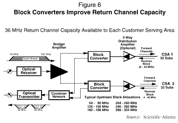
Another method which currently offers a commercial solution is a block converter (see Figure 6). Block converters multiplex the return path information from the distribution branches so that they can be carried back by one fiber (or one active and one standby fiber). Although block converter equipment is readily available, it does not appear to be necessary in many applications. As indicated above, in most cases, it costs less to subdivide the customer serving area to get the needed reverse-path-per-subscriber bandwidth, and the level of network reliability is not degraded by the added block converter electronics.
Finally, in the case where there is a very large amount of contention for the use of the upstream channel in order to transmit large amounts of high-speed, bursty data, a media access protocol similar to those used by local area networks can be adopted.
NEW SERVICES AND/OR INCREASED DEMANDS
The distribution capacity of hybrid fiber coax networks can easily be increased to accommodate either new subscriber services and/or increased service demand.
There are many techniques that can be used to enable the existing network to handle future service demands. Some of the techniques available for system design include:
These techniques can be applied in many different combinations to solve unforeseen future requirements.
ADDING NEW SERVICES
Broadband carrier distribution technology is extremely flexible in that the network does not have to provide either rate or protocol adaptation for information providers to be able to communicate with information users. The only prerequisites for communications are:
Of course, when signal switching is required, the switching functionality must also be compatible with the broadband carrier distribution plant.
COMPRESSION WILL SLOW CAPACITY DEMAND GROWTH
Video compression requires a compromise between the bandwidth of the compressed signal and the cost of the electronics required to decompress the signal so that it can be viewed.18 In order to achieve less bandwidth, more signal compression is needed. This increases the amount of real-time signal processing that must be performed on the signal before it is transmitted and after it is received. Compressed digital video signal bandwidth requirements will continue to fall as the cost of computer processing power and random access memory (RAM) storage decreases.
NETWORK POWERING
The introduction of fiber optics into the cable and telephone companies' networks created a new problem. Without the metallic connection back to the headend or the central office, there was no easy way to bring power out into the distribution plant. The telephone and the cable industries solved this problem in different ways.
The telephone industry developed a high-reliability "life-line" service solution for powering remote network facilities. These systems offer comparatively large amounts of power to supply current to the digital loop carrier remote electronics and to provide the ringing current required for the telephones. The cable industry, on the other hand, had no "life line" service requirements and relatively low current requirements.
As CATV system operators contemplated modifying their networks to carry telephony and other advanced services, a number of difficult technical and business decisions had to be made: the remote network power units would require reliability and power capabilities comparable to that used by the telephone industry. This meant that the remote power systems would be much more expensive than those normally used by the industry. Furthermore, it meant that the industry had to deal not only with the design of the distribution plant, but also with the design of the companion power distribution plant. Power nodes now have to be located so as not to be obtrusive to the customer and still perform adequately for the network.
A TELEPHONY APPLICATION
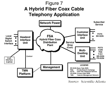
There are a large number of equipment manufacturers that currently are developing products which will allow residential and small business telephone services to be provided by a CATV distribution system. Such systems typically consist of two media adaptation devices: a Headend Interface Unit (HIU) and a Customer Interface Unit (CIU). The CIU is usually designed to attach to the side of a residence, providing standard telephone service to the subscriber. In order to improve the reliability of the telephone service, networks offering telephony usually invest in a high-reliability remote network powering system, and they usually employ protected routing between the headend and the serving area fiber node. A typical system is described in Figure 7.
A MULTISERVICE DISTRIBUTION SYSTEM An example of a network that can provide the broad range of information services and formats that are used in the communications industry today is provided in Figure 8. This network is capable of interfacing with high-speed equipment such as ATM, Frame Relay, and Packet switches as well as with narrowband ISDN and voice switching equipment. It can also interface directly with SONET OC-3 facilities and TR-8 local digital switches.
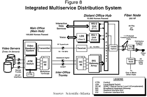
A key element of the hybrid fiber coax network that has not yet been described is the Broadband Integrated Gateway (BIG) and the Connection Management Controller (CMC -- not depicted for simplicity). The BIG performs two basic functions:
The CMC provides the BIG with the necessary information to take the data from the incoming ATM bit streams and route it to a subscriber in a serving area.
The BIG interfaces with the ATM switch using SONET OC-3 transport facilities. In this application, the switch routes ATM-compatible information from the video servers to the BIG. It converts the ATM cells into a format that is compatible with both existing NTSC video signals as well as the home communications terminals which are used to order switched digital video services interactively.
This simplified network diagram is part of a system that was designed to distribute up to five Gigabytes per second (42,000 Megabits per second) of video-on-demand and other digital information services in real time. The installed first cost of the network was only $750 per subscriber. This price included central office equipment for ATM and voice switching, headend equipment, the distribution equipment (including high-reliability remote powering), as well as the cost of the cable telephony equipment.